

How Cooling Channel Design Affects PET Preform Mold Cycle Time
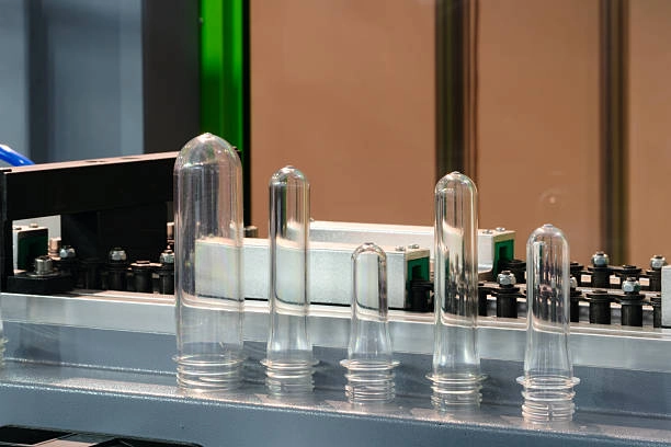
A PET preform line rarely loses capacity because the injection unit is too slow. Cooling is often the real constraint. Cooling channel design controls how quickly that heat leaves the mold. It also affects neck accuracy, clarity, wall thickness, and ejection stability.
For manufacturers using PET preform molds, cooling should be treated as a core part of mold engineering. It is not a finishing detail added after the cavity layout is complete.
What Is PET Preform Mold Cycle Time?
Cycle time is the period required to produce one complete molding cycle. It includes mold closing, injection, holding, cooling, mold opening, and ejection.
The Main Stages of an Injection Molding Cycle
The injection stage fills the cavities with molten PET. Holding pressure then compensates for material shrinkage while the gate remains effective. Cooling follows. The preform must hold its shape before the mold opens.
A simple calculation is:
Total cycle time = injection time + holding time + cooling time + mold movement and ejection time
If cooling takes 12 seconds and the rest of the cycle takes 6 seconds, cutting cooling by one second improves the total cycle by about 5.5 percent. That matters across a 48-cavity mold.
Why PET Preforms Need Precise Cooling
PET preforms do not cool at the same rate in every area. The neck and thread section have concentrated steel mass. The gate region often retains heat. Long core pins can become difficult to cool evenly.
How Cooling Channels Remove Heat from a PET Preform Mold
Molten PET transfers heat into the cavity, core, inserts, and surrounding mold steel. Coolant moving through the channels absorbs that heat and carries it to the chiller.
Cooling performance depends on channel spacing, diameter, coolant velocity, circuit length, and flow balance. The inlet temperature matters. So does the temperature difference between inlet and outlet.
Fast cooling is not automatically good cooling. One cavity area can become cold while another stays hot. That thermal imbalance may shorten one part of the cycle while increasing rejects. Uniform heat removal is the practical target.
Five Cooling Channel Design Factors That Influence Cycle Time
Several design choices determine whether the mold can remove heat efficiently. They should be considered together rather than adjusted one at a time.
1. Channel Distance from the Cavity
Cooling channels need to be close enough to remove heat quickly. They also need sufficient steel around them for strength and sealing.
The ideal distance changes with the preform shape, insert dimensions, steel grade, and working pressure. Around a thin preform wall, excessive distance creates a delayed cooling response. Around a threaded neck ring, poor spacing can leave a local hot zone.
2. Channel Diameter and Layout
A small channel can restrict flow and create a high pressure drop. A very large channel may reduce coolant velocity and consume space needed for structural support.
Straight drilled channels are common because they are easy to manufacture and maintain. They are not always thermally balanced. Parallel circuits may cool one side of a mold faster than the other if their lengths or fittings differ.
In a multi-cavity mold, balanced circuits help keep cavity temperatures closer together. That reduces cavity-to-cavity variation and makes process adjustments more predictable.
3. Coolant Flow Rate and Turbulence
Coolant moving in a turbulent pattern generally transfers heat more effectively than slow laminar flow. The exact flow rate depends on the channel size, coolant type, pump capacity, and pressure-drop limit.
A practical test is to record flow and temperature for each circuit. If one circuit shows a much higher outlet temperature, it may be carrying more heat. If its flow is weak, the channel may be undersized, restricted, or poorly connected.
The hot runner system also affects the cooling load. A balanced hot runner can reduce local heat concentration near the gates and make the cooling system easier to tune.
4. Cooling Around Cores, Necks, and Inserts
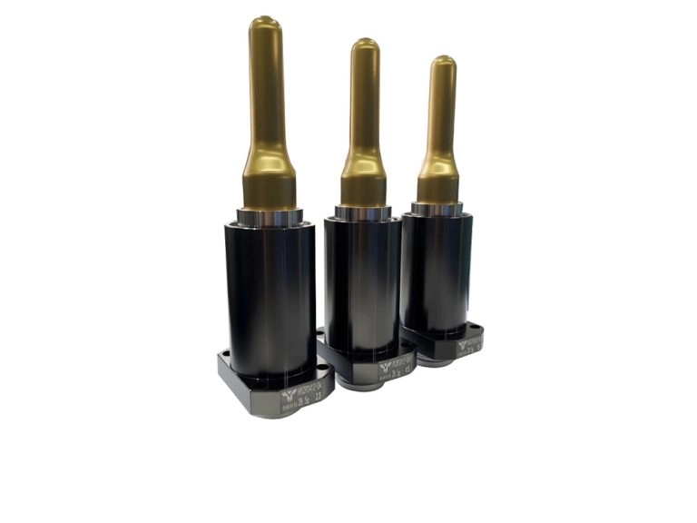
Core cooling often decides the cycle time in PET preform production. Long cores have limited space for conventional passages. Heat can remain trapped near the tip or around the neck finish.
Dedicated circuits for core inserts, neck rings, and gate areas can improve temperature control. In some designs, baffles or bubblers direct coolant into narrow regions. A useful observation from production trials is that the hottest component is not always the largest one. A small insert with poor flow can control the timing of the whole mold.
5. Conformal Cooling and Advanced Inserts
Conformal channels follow the cavity profile more closely than straight drilled passages. They can provide a more even distance from the molding surface, especially around complex neck geometry or dense cavity layouts.
The benefit is not guaranteed. Conformal inserts cost more and require suitable manufacturing methods. They also need attention to sealing, inspection, and long-term maintenance.
The Link Between Cooling Uniformity, Quality, and Productivity
Cycle time only matters when the parts remain within specification. A preform that cools unevenly may leave the mold quickly but fail during inspection or blowing.
Common symptoms include neck ovality, inconsistent thread dimensions, wall-thickness variation, haze, and ejection marks. Thermal stress can also appear later in the process. The defect may be blamed on the PET grade or machine settings when the real cause is a cavity that runs several degrees hotter than its neighbors.
Quality checks should include preform weight, neck dimensions, ejection temperature, visual clarity, and reject rate. Measuring only the machine cycle counter gives an incomplete picture.
How Engineers Optimize PET Preform Mold Cooling
A reliable optimization process starts with a thermal map. Simulation can identify hot regions before steel is cut. Production measurements then confirm whether those predictions match the real mold.
Engineers typically:
-
Locate hot spots around the gate, neck, and core.
-
Set channel positions while protecting insert strength.
-
Calculate flow rate and pressure drop for each circuit.
-
Separate circuits where one region needs different control.
-
Measure inlet temperature, outlet temperature, and cavity temperature.
-
Adjust coolant settings together with injection and holding parameters.
Cooling design must also respect ejection access and maintenance. A channel that performs well on paper but cannot be flushed or inspected becomes a service problem later.
Choosing a PET Preform Mold Manufacturer
The right supplier should understand the connection between cooling and the complete mold system. Ask how the manufacturer balances cavity circuits. Ask whether thermal analysis is available. Review how core cooling, hot runner layout, and inspection data are documented.
Experience with high-cavity PET molds matters because small temperature differences become significant when dozens of cavities run continuously. Support after delivery matters as well. A cooling restriction or leaking fitting can erase the expected cycle-time gain.
This is where custom mold design support from HEYAN TECHNOLOGY can enter the discussion. Share the preform weight, neck finish, cavity count, target output, and current cycle data. Those details give the engineering team a basis for recommending a practical cooling layout.
Conclusion: Better Cooling Design Creates Faster, More Stable Production
PET preform mold cycle time is strongly affected by the way heat moves through the mold. Channel distance, circuit balance, coolant flow, core cooling, and insert design all contribute.
The best result does not come from adding more channels. It comes from matching the cooling system to the cavity geometry and the production target.
For a new mold or an existing line with a stubborn cooling delay, contact HEYAN TECHNOLOGY with the current cycle data and preform drawings. A focused cooling review may reveal the extra seconds hidden inside every cycle.
FAQ
Q: Does cooling channel design affect PET preform quality?
Yes. Uneven cooling can cause warpage, haze, ovality, neck deformation, and unstable ejection.
Q: What is the best cooling channel diameter for a PET preform mold?
There is no universal diameter. The correct size depends on channel length, coolant flow, pressure drop, steel thickness, and mold geometry.
Q: Can conformal cooling reduce PET preform cycle time?
It can improve heat-transfer uniformity in complex areas. The actual gain depends on the complete insert design and process conditions.
Q: How can I reduce PET preform mold cycle time?
Measure cavity temperatures, coolant flow, outlet temperature, and ejection temperature. Then optimize the cooling circuits together with hot runner and machine settings.