
Ultimate Guide to Injection Molding Tolerances for Multi-Cavity Production
Once you move from single-cavity tools to multi-cavity injection molding, injection molding tolerances stop being a small note on the drawing. They start to decide your scrap rate, complaint rate, and how stable your line runs across long shifts. If tolerances are too loose, parts rattle, leak, or look cheap. If they are too tight, the mold becomes difficult to run and every small change in material or temperature shows up in your measurements.
This guide walks through how tolerances work in multi-cavity production, what really drives dimensional variation, and how you can keep a practical balance between cost and precision. The focus is simple: give you enough technical depth to talk with designers and toolmakers, but in a way that still matches daily production reality.
What Are Injection Molding Tolerances?
Injection molding tolerances are the allowed deviations from the exact size and geometry of your plastic parts. Instead of one fixed value, each feature gets a tolerance range, often written as a plus or minus around the nominal dimension. Industry guides and standards often mention typical ranges around ±0.1 mm for many plastic parts, with tighter bands down to about ±0.025 mm on critical work.
When you plan tolerances well, you keep injection molding dimensional accuracy under control and avoid endless debate during inspection. Poor planning gives you a drawing that looks perfect but cannot be met with real material behavior and real machines.
Key Types of Tolerances for Molded Parts
In dimensional tolerance injection molding, the first group you deal with is simple size: length, width, height, hole diameters, and similar values. These set the basic fit between parts. The second group is geometric tolerance injection molding, which talks about straightness, flatness, roundness, and position so that parts not only fit, but seat, seal, and move correctly.
On top of that comes tolerance stack-up. Several parts, each with small variation, can shift far more once assembled. If every part is drawn with a very tight tolerance range “just to be safe”, you end up with a tight tolerance plastic mold, higher tool costs, slower cycles, and little real gain.
Why Tolerances Are Not One Fixed Number
There is no universal “good” tolerance. A cover, a snap, and a sealing ring do not need the same band. Most suppliers treat standard dimensions with commercial tolerance, while a few key features move into fine or tight bands. In high-precision projects you may also describe targets as precision injection molded parts, but even then it is still a set of smart compromises, not magic numbers.
Why Do Tolerances Matter More in Multi-Cavity Production?
In a single-cavity tool you focus on how one cavity behaves over time. In a multi cavity injection mold, you must watch both time and cavity-to-cavity spread. Studies on multi-cavity injection molding show that variation between cavities and small shifts in machine settings often contribute more to length changes than normal shot-to-shot noise.
If one cavity runs hotter or fills earlier, you get different shrink and different dimensions even with the same nominal settings. That is why injection molding precision in multi-cavity work is as much about balance and multi-cavity consistency as about machining accuracy.
Cavity Variation and Real Output
Even a few degrees temperature difference or slight cooling imbalance can cause ovality, bow, or local warpage. When this happens in only part of the cavity bank, some parts pass, others drift slowly to the edge of your inspection window. You might see more flash, short shots, or other injection molding defects from certain cavities only.
So it becomes important to link your mold design for multi-cavity work with process control. Practical tools like an injection mold tolerance chart, regular dimensional checks per cavity, and basic mold flow analysis give you a simple way to see which cavities are near the edge and which still sit in the middle of the band.
Impact on Assembly and Customer Complaints
Tolerances matter most when your parts meet other parts. Threads, snaps, and seals are sensitive to small changes in diameter and length. If you ignore part shrinkage control or injection molding material shrinkage, assembly issues show up later as leaks, loose fits, or creaks that drive customer complaints. Tight numbers on paper are not the goal; stable and repeatable function is.
What Factors Control Your Injection Molding Tolerances?
Tolerances come from a mix of resin behavior, part geometry, tool build, and process stability. If you want realistic injection molding tolerances, you need to look at all of them together, not fix only one and hope for the best.
Material Shrinkage and Part Geometry
Different plastics shrink at different rates. Filled materials behave differently from neat resins. Standards and design guides often group materials into tolerance classes for this reason. If you want injection molding precision with a higher-shrink resin, then transitions, wall thickness, and rib design need extra care. Sudden thickness jumps often cause local sink and extra movement.
Smart part shrinkage control starts in the model. Smooth transitions, balanced walls, and thoughtful gate locations make it easier for the mold and process to hold the band you want.
Mold Design, Cooling, and Process Stability
Mold machining sets the baseline. Typical general-purpose tooling may be built around tolerances near ±0.1 mm, while tight work uses finer machining down toward ±0.05 mm or better. But the steel alone does not fix everything. Cooling layout, venting, and runner balance steer how the part cools and how repeatable the filling pattern stays.
Once the mold is in the press, repeatable clamp force, melt temperature, and packing pressure finish the picture. If those drift, even a very good tool cannot keep close tolerance bands.
How to Work with Tight Tolerance Injection Molding?
Tight tolerance injection molding should start on the drawing, not during fire-fighting on the shop floor. The key is to flag only the truly critical features. Ask which dimensions affect sealing, safety, and assembly, and give those the narrow bands. The rest can use a more relaxed band that still looks professional but is easier to meet in real volume.
Setting Realistic Tolerances on Drawings
Before you send a part out for tooling, look at your own drawing like a process engineer would. If everything is called out as fine or high-precision, you almost guarantee trouble later. A short note that points out key inspection dimensions, plus a simple injection mold tolerance chart shared with your supplier, reduces argument later and fits real process capability.
Practical Steps on the Shop Floor
On the floor, tight work acts like a magnifier. Small changes in drying, melt temperature, or mold temperature show up quickly in your checks. For this reason, many plants treat precision injection molding runs with fixed start-up routines, locked process windows, and regular checks on part weight and at least one critical dimension per cavity. It does not have to be fancy, but it does have to be consistent.
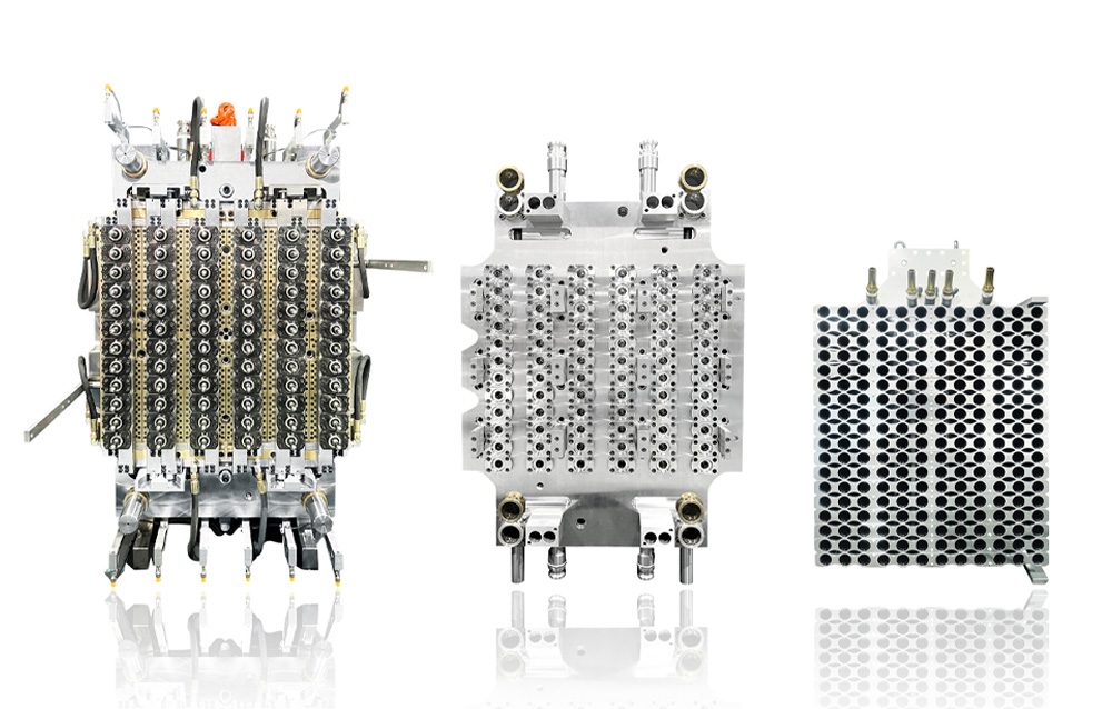
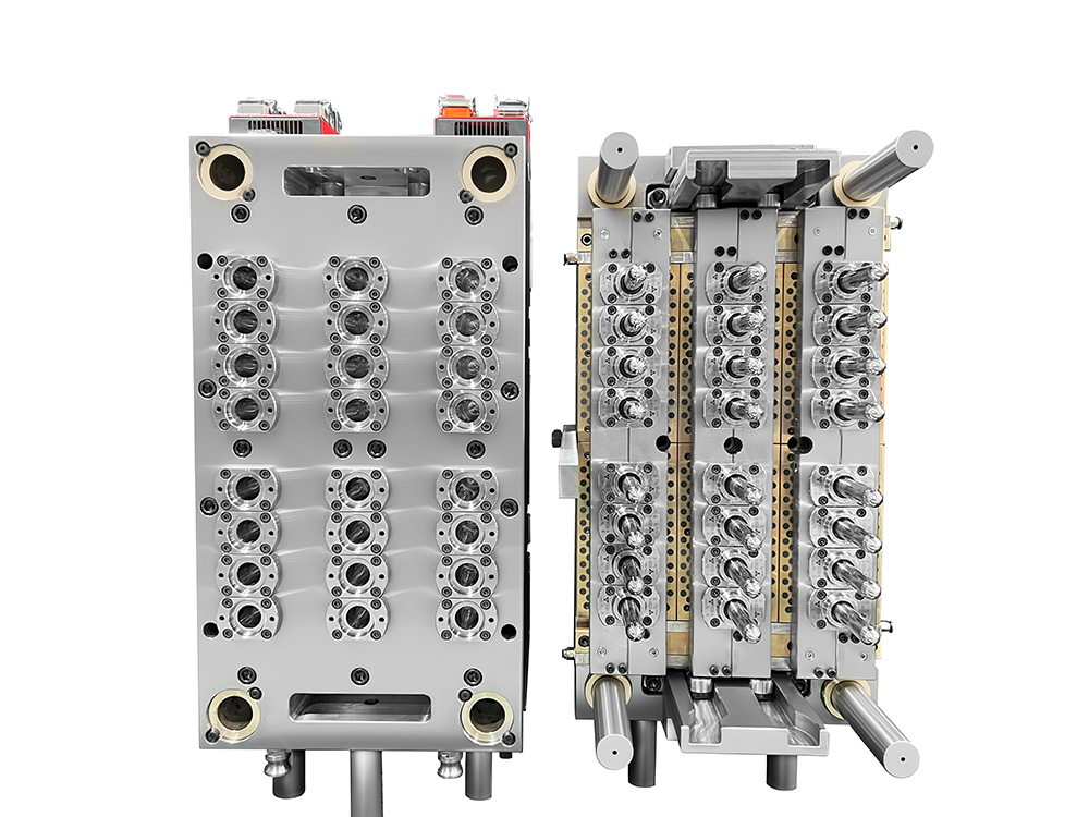
How Multi Cavity Injection Mold Design Supports High-Cavity Preform Tooling?
High-cavity preform tooling pushes all of these ideas to the edge. As cavity count grows, tiny differences in filling and cooling start to matter a lot more. A modern multi cavity injection mold for narrow-neck work, for example, must keep neck diameter, thread geometry, and body length tightly grouped so downstream blowing or filling equipment does not need constant adjustment.
Here, the combination of balanced runner design, solid cooling coverage, and clear thinking about injection molding tolerances is what lets you run volume without constant tweaking.
Cavity Layout, Cooling, and Tolerance Targets
Experience and research on multi-cavity tools point to simple rules: symmetrical layout, balanced flow paths, and cooling channels that treat each cavity in the same way. If you follow those rules, it becomes realistic to talk about tight tolerance injection molding for key features, while keeping other, less sensitive areas in a wider band.
In this kind of work, you usually care most about weight variation, neck dimensions, and straightness. Once you see stable results there, you can treat “preform tooling” as a known platform rather than a constant experiment.
Introduction to HEYAN TECHNOLOGY
HEYAN TECHNOLOGY (Foshan Heyan Precision Mold Technology Co., Ltd.) focuses on high-performance tooling for beverage packaging and related plastic products. The company combines design, engineering, and manufacturing, so feedback from mass production can feed back into mold design for multi-cavity projects. Its portfolio covers high-cavity molds for closures, preforms, and other technical parts where stable output and long tool life matter just as much as raw cycle time.
For plants that care about consistent weight and geometry, HEYAN TECHNOLOGY offers precision injection molding support from early part review through trials and ramp-up. Its multi cavity injection mold designs focus on balanced filling, solid cooling, and easy maintenance, so you can keep running instead of stopping for small fixes. When you need help with high-cavity preform tooling or other tight tolerance injection molding jobs, the team can adjust details to your line, rather than forcing you into a one-size-fits-all layout.
FAQ
Q1: What is a reasonable starting point for injection molding tolerances?
A: Many general plastic parts run well with a starting band around ±0.1 mm on main dimensions, while very critical features may use bands closer to ±0.025 mm, based on common industry tables and standards. If your part does not seal or carry high loads, there is usually no need to push everything into the tightest group.
Q2: Do all dimensions need tight tolerance injection molding?
A: No. You only need very tight bands on features that control fit, sealing, or safety. Cosmetic edges and non-critical ribs can use a wider band. This approach lowers tool cost and makes it easier to keep the process stable, especially when you run a multi cavity injection mold at high speed.
Q3: How does multi-cavity injection molding affect part variation?
A: Multi-cavity injection molding multiplies small differences in temperature, flow, and packing. If cooling or runner balance is off, you may see one group of cavities running slightly heavy and another light or short. Regular checks by cavity and a basic mold flow analysis during development help you spot and correct these patterns early.
Q4: Why do drawings mention things like dimensional tolerance injection molding and geometric tolerances?
A: Those notes tell your tooling and process teams how much variation is allowed in both size and shape. Dimensional values define the simple plus and minus on length and diameter, while geometric values set limits for flatness, straightness, and position. Together, they guide machining, process setup, and inspection.
Q5: What should you ask a supplier if you need high-precision molds for multi-cavity work?
A: You can ask about typical tolerance bands they hold on critical features, their experience with tight tolerance plastic mold projects, what materials and steel grades they use, and how they monitor cavity-to-cavity variation over time. It is also useful to talk about spare parts, support during sampling, and how often they recommend service on high-output tools.